Earth – Earth Resistance Tester – Construction, Working and Applications
Ground or ground resistance testers play a vital role in assessing the effectiveness of earthling and grounding systems by measuring ground resistance and soil resistance. For a proper grounding and grounding system, it is essential to measure and maintain the appropriate earth resistance and earth resistance.
In power systems and electrical installations, all machines and external metal bodies are connected to an effective earth rod/earth electrode. In the event of a fault, the leakage current will easily pass to the earth source, thus protecting the person working on the machines and equipment.
Earth resistance
Earth resistance refers to the resistance between the grounding electrodes and the earth. Earth has zero resistance due to its large cross-section (i.e, Earth’s resistance is assumed to be zero for comparison). Since the ground resistance is zero, the ground potential is assumed to be zero as well.
The resistance between the ground and the ground rod / ground electrode depends on the following.
- Internal resistance of earth electrodes / earth rods (almost negligible).
- Contact resistances between electrode and ground.
- Soil resistance between the two electrodes on which the measurement is made.
However, the electrodes themselves have a very low (or negligible) resistance. Similarly, the soil resistance between the electrodes is almost negligible. In reality, ground resistances consist of transition resistances between electrodes and ground.
What is an earth/earth tester?
A grounding tester, also known as an earth resistance tester or earth resistance meter, is an essential tool used to determine earth resistance and earth resistance for grounding and grounding systems.
This is a modified version of the Megger (also known as an earth megger) which is used to measure and calculate the earth resistance between earth, earth rod/earth electrode and wiring installations.
Ground testers range from zero to 50 ohms, zero to 500 ohms, zero to 1500 ohms, and zero to 3000 ohms. They are available in digital and analog formats, while the old-school ones are manually operated.
Construction of earth resistance testers:
Modern digital earth resistance testers, such as those made by Megger or Fluke, are typically handheld devices with a rugged construction designed to withstand field conditions and include a variety of built-in features.
The construction of a ground tester is similar to a megger, except that a megger has two terminals, while an earth/ground resistor may have three or four terminals.
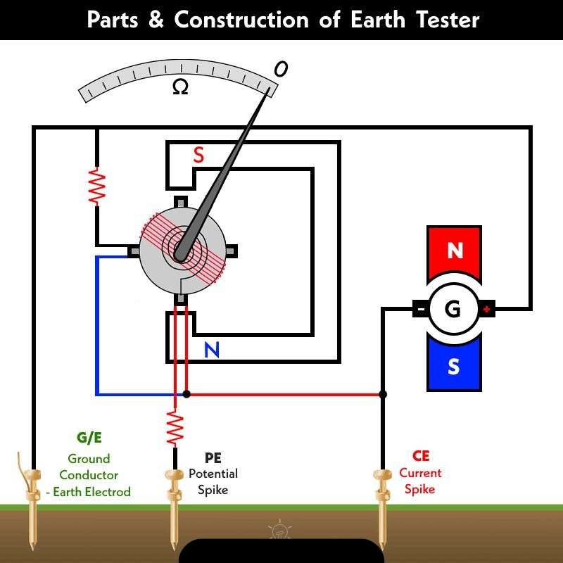
Old manual earth testers consist of a manually controlled DC generator, a current coil, a potential coil, a fixed resistance, a current limiting resistor, a permanent magnet and a pointer scale.
The potential and current coils are fixed on a common axis, form an angle of 90° and move freely inside the magnetic field created by the magnets. The deflection (pointer) of the ground tester is always at zero.
Key components include:
- Current Source: Generates a controlled current that is injected into the ground.
- Voltage measurement circuit: Measures the potential difference between the grounding electrodes.
- Display Unit: Displays the earth resistance value in ohms or other relevant units.
- Controls and Settings: Allows users to configure test parameters and select measurement modes.
Principles of earth resistance tester work
Earth testers work based on Ohm’s Law, where the measured earth resistance (R) is determined by dividing the potential difference (V) by the injected current (I). The formula is expressed as R = V/I. Based on these principles, the tester automatically calculates the earth resistance.
A specific current is injected into the tip “CE” and the ground electrode/ground rod “E/G”, both located at a specific and equal distance inside the ground. The potential spike “PE” is placed between the current spike “CE” and the ground rod or ground electrode “GE”. It now measures the potential difference between the “PE” potential tip and the “GE” earth/earth electrode. Using Ohm’s law, earth resistance can be calculated as follows.
RE = V ÷ I
Where
- RE = Ground / Earth Resistance
- V = Potential Difference
- I = Current
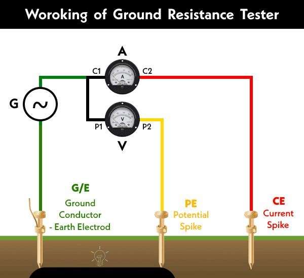
When the “Test/Measure” button is pressed (or for hand-held testers, when the handle connected to the generator rotates at a uniform speed, i.e. 160 revolutions per minute), current is injected and flows through the CE electrode (via C1 and C2) and the ground electrode “G /E”. Pressure coils P1-P2 are installed between tip P and ground. Since there is no voltage drop across the CE tip, the drop in transient resistance affects the pressure coil, which moves the pointer and shows the readings. These values are not affected by ground resistance.
Note that ground resistivity decreases rapidly with temperature and ground salt concentration; therefore, a mixture of salt and charcoal is added to the earth pit to reduce the earth resistance value.
Electrode placement:
Correct electrode placement is essential for accurate ground resistance measurements. The Winner 4-point method is commonly used, which involves an arrangement of four equally spaced electrodes. The distance and depth of the electrodes play a significant role in obtaining reliable results.
Generally, the distance between the spikes and the electrode is three times the length of the ground rod or ground electrode. Alternatively, the tip length should be 1/3 the distance between the tips.
Example:
If the distance between the tips is “a”, the length of the rod or electrode should be 1/3 “a”.
Length of Ground Rod = 2.5 m (8.2 ft.)
Distance between the spikes and rods = 7.5 m (24.6 ft.).
Always refer to the user manual for the desired model or consult a licensed electrician to ensure compliance with proper codes and guidelines.
Conclusion
The conclusion from the use of the earth resistance tester is whether the earthling system meets the required standards and is safe for operation. If the measured resistance is within the acceptable limits set by the relevant regulations or standards, then the grounding system is considered adequate. If the resistance is too high, it may indicate a bad ground, which may need to be addressed to ensure electrical safety.
In short, the ground resistance tester helps to evaluate the effectiveness of the grounding system, to ensure the safety and proper functioning of electrical installations.